Device Profiles
Device Profiles define how the Network Server manages the LoRa operational parameters of one or more Devices.
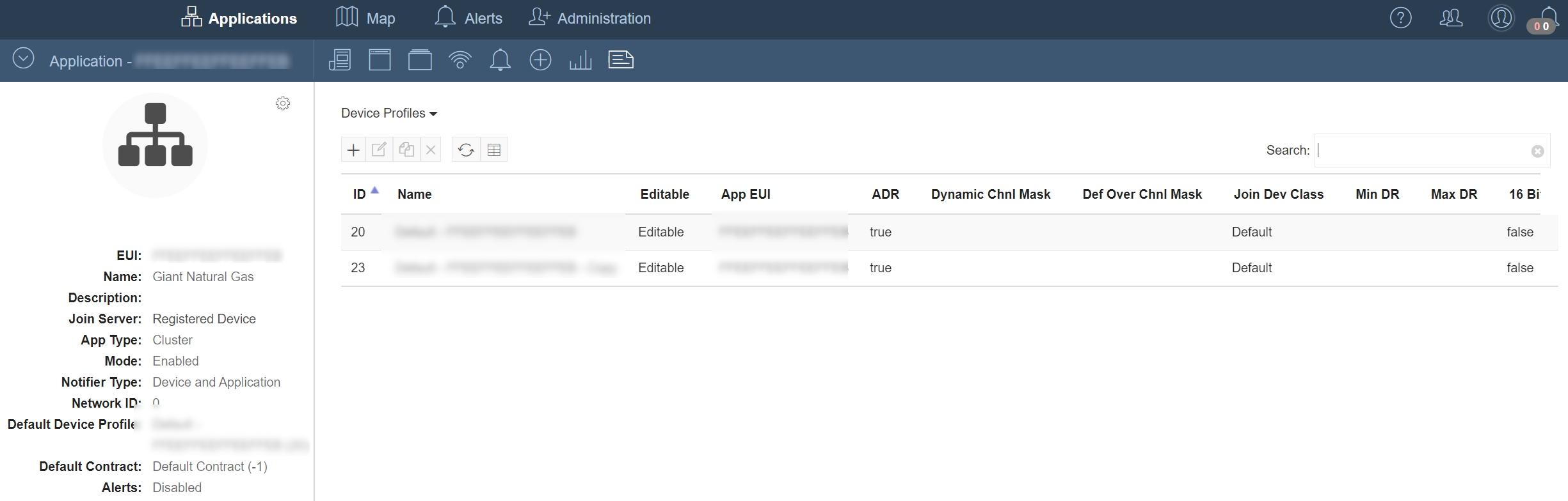
Setting Device Profiles
-
Profiles are set as part of Device registration or activation.
-
Device Profiles are enforced continuously. Once assigned they take effect upon successful join and through ongoing evaluation of all uplinks thereafter.
Adding Device Profiles
To add a new Device Profile click the  button and fill in the required information.
To edit a Profile, highlight the row and click the  button.
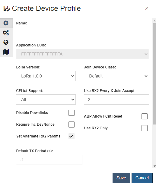
Base Settings
When editing or adding a Profile click on the  to configure its base settings.
| Field | Description |
|---|---|
| Name | Descriptive name displayed in the Device and Application information associated with the Profile. |
| Application EUI | The EUI of the Application that this Profile is restricted to. |
| LoRa Version | The version of the LoRaWAN stack that the Device supports. |
| Join Device Class | The LoRaWAN Device class that the Device is after joining the network for OTAA Devices, or when it first uplinks the first time for ABP Devices. Default is Class A for LoRaWAN currently. The other options are Class B and Class C. |
| CFList Support | This option identifies the type of CFList allowed for use. The CFList is provisioned only when supported by the region the device is operating in. If Type 0 is selected, the CFList will be used for regions implementing dynamic channel plans (EU868, AS923, IN865, CN779, EU433, KR920 and RU864). The Type 1 CFList is only supported for regions implementing fixed channel plans (US915 and AU915). |
| Disable Downlinks | This option will stop the network server from ever sending a downlink to the Device. This is mainly used for testing how a Device will behave if you starve it of downlinks. |
| ABP Allow FCnt Reset | If enabled, this option allows the network server to still process uplinks for an ABP Devices that re-use a previously used FCnt. This can happen if an ABP Devices does not save its frame counter when it is rebooted. |
| Require Inc DevNonce | This option forces that a Device always increments its DevNonce on a join request, instead of using a random key. |
| Use Rx2 Only | This option will force the network server to always respond to the Device on RX2. |
| Set Alternate RX2 Params | This option enables sending alternate parameters in Class B downlinks. |
| Default TX Period(s) | The interval at which the Device is expected to transmit uplinks at. This is used for calculating PSR when packets were lost at the end of the day. |
| Max Retransmits | The maximum number of retransmits that a Device can send prior to dropping the uplinks with the same sequence number. |
| Description | A custom text field to provide a summary of the Device Profile purpose. |
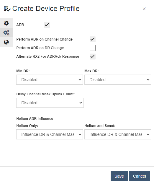
ADR Settings
When editing or adding a profile, click on the  to configure its ADR (Adaptive Data Rate) settings.
| Field | Description |
|---|---|
| ADR | Checkbox to tell if the Devices that use this profile support receiving the LinkAdrReq MAC command from the network server. |
| Perform ADR on Channel Change | This flag controls whether the network server should perform an ADR re-evaluation if a Device is detected communicating on a channel outside its configured range. |
| Perform ADR on DR Change | This flag controls whether the network server should perform an ADR re-evaluation if the Device is detected communicating at a data rate different from its configured rate. |
| NBTrans | The number of transmits to tell a Device to use to send each uplink to ensure it gets to the network server. |
| Min DR | The minimum data rate the network server is allowed to command the Device to use. |
| Max DR | The maximum data rate the network server is allowed to command the Device to use. |
| Delay Channel Mask Uplink Count | The number of uplinks to wait after a Device joins before assigning a channel mask. This allows the Netmore LNS to select the optimal Base Stations hearing a Device to generate a more inclusive channel mask. |
| Helium Only | This controls whether uplinks from Devices exclusively heard on the Helium network are allowed to influence ADR. The option allows for packets received through Helium only will influence both Data Rate and Channel Mask. |
| Helium and Senet | This controls whether uplinks from the Helium network, from Devices heard on both the Helium and Senet networks, are allowed to influence ADR. The options allow for selecting whether Helium uplinks influence DR alone or also impact optimal channel mask selection. |
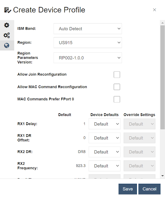
LoRa Regional Settings
When editing or adding a profile click on the ![]() to configure its LoRa region specific settings.
to configure its LoRa region specific settings.
| Field | Description |
|---|---|
| ISM Band | This is used for regions where a Device might be heard on multiple bands. When set, the Network Server will only process uplinks on the designated band to ensure optimal ADR configuration. |
| Region | The LoRaWAN radio frequency region - as defined in the LoRaWAN Regional Parameters Specification - where the Device will be operating. |
| Region Parameters Version | Identifies the version of the LoRaWAN Regional Parameters specification that the Device operates in compliance with, according to its regional location. |
| Allow Join Reconfiguration | If enabled, allows the LNS to configure the RX 1 Delay, RX 1 DR Offset, and RX 2 DR in the join request. |
| Allow MAC Command Reconfiguration | If enabled, allows the LNS to use RXTimingSetupReq, RXParamSetupReq, TxParamSetupReq, DutyCycleReq, PingSlotChannelReq, and BeaconFreqReq MAC commands to be used to reconfigure a Device. |
| MAC Commands Prefer FPort 0 | If enabled or the MAC command length exceeds 15 bytes, the Senet LNS sends downlinks that only contain MAC commands in the Application payload and uses FPort=0. If this is not enabled, MAC only commands 15 bytes or less in length are sent to the Device in the fopts portion of the downlink. |
| Default | This column reflects the RF region's default values defined in the LoRaWAN Regional Parameters Specification that Devices are expected to employ when either joining the network via OTAA, or being provisioned onto the network via ABP. |
| Device Defaults | Configuring this column’s values allows the LNS to accommodate manufacturer settings for Devices that do not implement the LoRaWAN-specified regional defaults when either joining the network via OTAA, or being provisioned onto the network via ABP. |
| Override Settings | This column’s values define a target configuration the LNS will command after a Device successfully joins the network. For the duration of the Device Profile assignment, the LNS compares the Device's current state (as reflected by its uplinks) to these settings and will reassert this configuration to the Device via MAC commands accordingly. |
| RX1 Delay | The delay in seconds for the Device to wait after the transmitting a class A uplink to wait for the RX1 window of its Class A downlink. The RX2 delay is this delay plus 1 second. This setting can be set during the join of a Device or via a downlink of an RxTimingSetupReq. |
| RX1 DR Offset | The DR offset to be applied to the formula to figure out the DR to respond to the Device's uplink. This can be used with Asymmetric Link Budget to allow a Device to better hear downlinks. This setting can be set during the join of a Device or via a downlink of an RxParamSetupReq. |
| RX2 DR | The DR the Device should listen on for its RX2 reception window. This is also the DR used by Class C downlinks. This setting can be set during the join of a Device or via a downlink of an RxParamSetupReq. |
| RX2 Frequency | This is the frequency the Device should listen on for its RX2 reception window. This is also the DR used by Class C downlinks. This setting can only be set via a downlink of an RxParamSetupReq. |
| Dwell Time | This is the setting used to configure if the Device needs to obey a 400ms uplink and/or downlink dwell time. This setting is only applicable in some regions, such as AS923 and is only required in some countries within that region. This setting can only be set via a downlink of an TxParamSetupReq. |
| Duty Cycle | This is used to configure the maximum duty cycle that a Device should operate at. This can be used for Device that no longer have service to tune down the number of uplinks. This setting can only be set via a downlink of an DutyCycleReq. |
| Max EIRP | This value is used to configure the maximum EIRP a Device calculates it max transmit power from. The ADR algorithm is Max EIRP - (2 x LinkADRReq->TxPower). This setting can only be set via a downlink of an TxParamSetupReq. |
| Channel Mask | This is used to tell which channels a Device should configured to use. The value is a hexadecimal value where the binary representation of the value has a bit per channel, with channel 0 being the right most bit. For example, 06 would be represented as 00001010 in binary. This has channel 0 disabled, channel 1 enabled, channel 2 disabled, channel 3 enabled, and channels 4, 5, 6, 7 as all disabled. This setting can only be set via a downlink of a LinkADRReq. |
| Ping Slot Frequency | This is the frequency that a Class B Device should be listening on for receiving a downlink on one of its ping slots. Setting this value in regions that require frequency hopping will cause the Device to only listen on the static frequency. This setting can only be set via a downlink of a PingSlotFreqReq. |
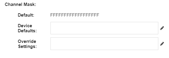
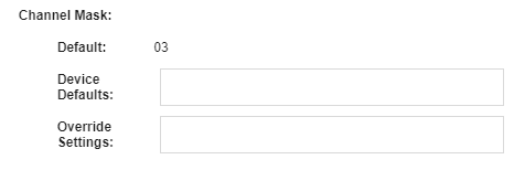
Channel Mask
In this section, the current settings for which channels are enabled or disabled are displayed and controlled, with respect to the following:
-
Default: Expected default channel plan for the selected region.
-
Device Defaults: Expected default channel plan for the Devices not compliant with the regional default.
-
Override Settings: Channel plan to be commanded by LNS after the Device(s) successfully joins the Network.
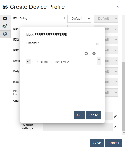
Editing
For the US915 and AU915 fixed Channel Plan regions, the Device Defaults and Override Settings may be updated using a custom channel mask editor, indicated by the pencil icon to the right of the respective fields:
Clicking the pencil launches the editor, wherein the Channel Mask located at the top will dynamically update in response to changes:
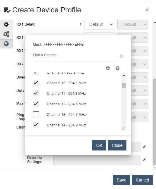
The editor also supports filtering the list, making it easy to find and update specific channels:
For all other regions, the Channel Mask is directly entered as a 2 or 4-character hexadecimal string:
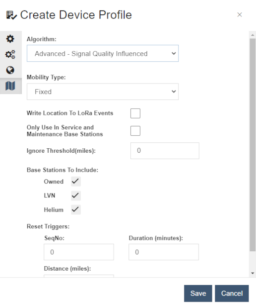
Estimated Location Settings
When editing or adding a profile click on the ![]() to configure its Estimated Location algorithm settings.
to configure its Estimated Location algorithm settings.
Options to select and configure the algorithms used to determine the estimated location of a Device are set in this section. Configuration options are only available for the Advanced - Signal Quality Influenced algorithm.
Algorithms
| Algorithm | Description |
|---|---|
| Basic - Simple Location Average | Centroid of the Base Stations hearing the Device. |
| Advanced - Signal Quality Influenced | This algorithm uses the Base Station RSSI value to weight an uplink. Base Stations with a better RSSI will be weighted slightly higher and shift the Device location in that direction. Each RSSI weighted location is added to a running total. |
Advanced Algorithm Options
| Option | Description |
|---|---|
| Mobility Type | Fixed - The Device is positioned at a fixed location and is not expected to move. Nomadic - The Device infrequently moves from location to location. Mobile - The Device frequently moves from location to location. |
| Write Location to LoRa Events | Toggle inclusion of the Device location in the LoRa Events. Required to show the Estimated Location view in Device Details. |
| Only Use In-Service and Maintenance Base Stations | Toggle inclusion of Base Stations by Administrative Status |
| Ignore Threshold(miles) | Ignore positional changes in location exceeding this value. |
| Base Stations to Include | Owned - Include owned Base Stations in location calculations. LVN - Include Base Stations that are members of the LVN in location calculations. Helium - Include Helium Hotspots in location calculations. |
| Reset Triggers | SeqNo - Reset estimated location calculations if the uplink sequence number exceeds this value. Duration- Reset estimated location calculations after this many minutes. Distance(miles) - Reset estimated location calculations if the location changes by this many miles. |