Base Station Management
The Base Station Tab allows a user to manage the Base Stations connected to the network. Through this management view the user has the ability to view statuses, details, and edit Base Station settings.
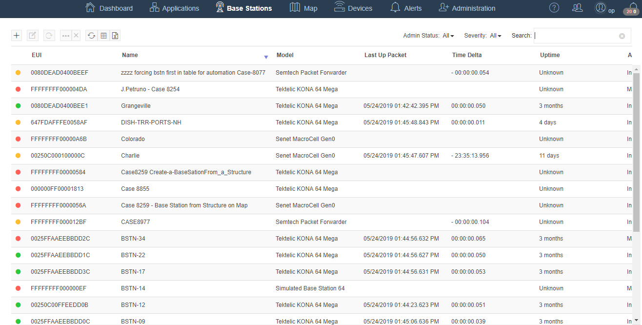
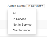
The default table shows a list of Base Stations configured for use on the network that have an Admin Status of In Service. To see all the Base Stations configured for the network, change the Admin Status on the top right of the table to All
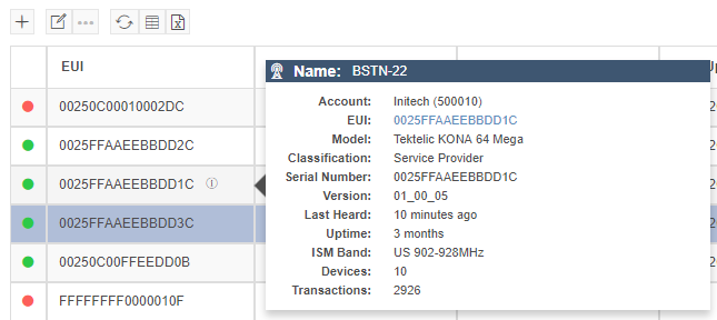
The first column of this table shows the connection status of the Base Station with a red or green dot. When there is an issue the mouse can be hovered over this dot to display more information on the connection status.
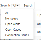
The Severity filter for the table can be used to selectively display conditions affecting Base Station status. These filter conditions are Base Stations with no issues, open alerts, open cases or connection issues.
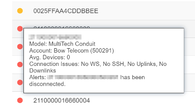
For a quick overview of a Base Station hover over the EUI and click the  icon to the right. This will then display a quick pop up of important information about the Base Station.
Base Station Details
For an in depth look at Base Station click on the Base Station EUI for the Base Station Details page.
Adding a Base Station
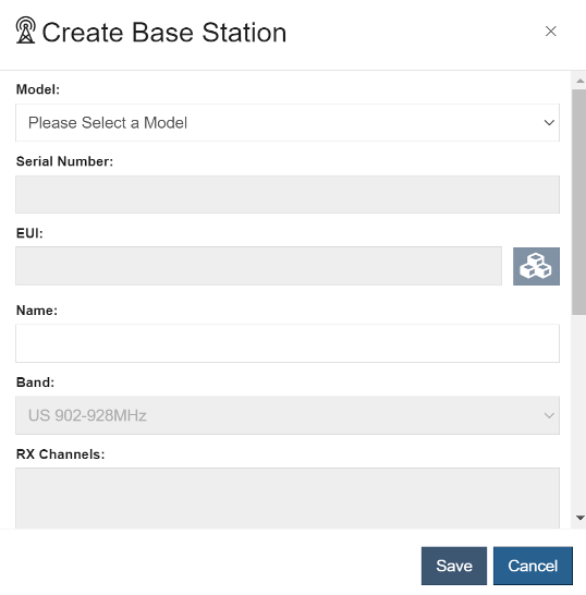
To add a new Base Station to the network click the  button at the top of the table and fill in the required information.
Bulk Provisioning Base Stations
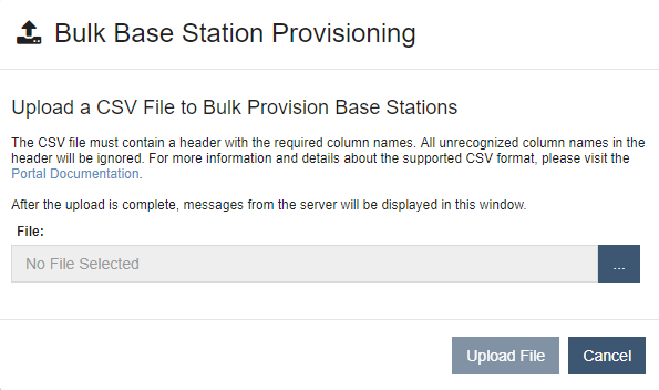
Multiple Base Stations can be provisioned by uploading a CSV file from the Base Station table. The file contains all the information needed to provision a site that is not currently deployed. Once the file is uploaded, the request is processed and the status of the request is returned to the user.
Note
Bulk operations are limited to one concurrent request per customer.
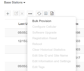
Click on the  button to open the menu. Select Bulk Provision from the dropdown menu.
This opens the Bulk Base Station Provisioning Dialog.
CSV File Format
| Parameter | Description | Required | Default Value | Allowed Values |
|---|---|---|---|---|
| eui | The IEEE EUI-64 identifier for the LoRa Base Station. | Yes | A valid hexadecimal string | |
| model | The Base Station model ID (See table below) | Yes | A valid Base Station model | |
| serialNum | The Base Station serial number whose format matches the format supported by the given model | Yes | A valid Base Station serial number that matches the Base Station model serial number format. | |
| ismBandName | A valid ISM band name to assign to the Base Station (See table below) | Yes | A valid ISM band name | |
| tags | Text identifiers added to a Base Station to assist in grouping and filtering | No | A comma separate list of tags | |
| channelConfig | Radio Channel Bank ID(s) to be used | No | 0 | Array Integer Value |
Base Station Models
| Model | Model ID | Serial Number Format | Example Serial Number |
|---|---|---|---|
| ADTRAN Micro 8 | ADTRAN_8 | XXXXXXXXXXXXX... | 1234567890ABCDEF |
| ADTRAN 64 | ADTRAN_64 | XXXXXXXXXXXXX... | 1234567890ABCDEF |
| Arduino Yun/Tian | ARDUINO_YUN | 0XXXXXXXXXXXXX | 0X01234567890A |
| Gemtek/Browan Femto | GEMTEK_PICO | XXXXXXXXXXXXXXX | 01234567890ABCDE |
| Kerlink iFemtoCell | KERLINK_PICO | 0XXXXXXXXX | 0X0F0F0F0A |
| Kerlink Wirnet iBTS 8 | KERLINK_IBTS_8 | 0XXXXXXXXX | 0X0F0F0F0B |
| Kerlink Wirnet iBTS 64 | KERLINK_IBTS_64 | 0XXXXXXXXX | 0X0F0F0F0C |
| Kerlink Wirnet iBTS Compact | KERLINK_IBTS_16 | 0XXXXXXXXX | 0X0F0F0F0D |
| Kerlink Wirnet iStation | KERLINK_IST | 0XXXXXXXXX | 0X0F0F0F0E |
| Kerlink Wirnet Station | KERLINK_IOTS | 0XXXXXXXXX | 0X0F0F0F0F |
| Ezurio (Laird) Sentrius | LAIRD_SENTRIUS | 0XXXXXXXXXXXXX | 0X0123456789AB |
| MultiTech Conduit | MULTITECH_CONDUIT | XXXXXXXX | F0F0F0F0 |
| MultiTech Conduit 16 IP67 | MULTITECH_CONDUIT_16_IP67 | XXXXXXXX | F0F0F0F0 |
| MultiTech Conduit 16 IP67 200 | MULTITECH_CONDUIT_16_IP67_2 | XXXXXXXX | F0F0F0F0 |
| MultiTech Conduit AP | MULTITECH_CONDUIT_AP | XXXXXXXX | F0F0F0F0 |
| MultiTech Conduit IP67 | MULTITECH_CONDUIT_IP67 | XXXXXXXX | F0F0F0F0 |
| Semtech Packet Forwarder | SEMTECH_PKT_FORWARDER | XXXXXXXXXXXXX... | 1234567890ABCDEF |
| Semtech Packet Forwarder 16 | SEMTECH_PKT_FORWARDER_16 | XXXXXXXXXXXXX... | 1234567890ABCDEF |
| Semtech Basic Station | SEMTECH_BASIC_STATION | XXXXXXXXXXXXX... | 1234567890ABCDEF |
| Semtech Basic Station 16 | SEMTECH_BASIC_STATION_16 | XXXXXXXXXXXXX... | 1234567890ABCDEF |
| Tektelic KONA 8 | TEKTELIC_KONA_8 | TXXXXXXX_XXXXXXXXX | T0123456_7890ABCDE |
| Tektelic KONA 16 Macro | TEKTELIC_KONA_16 | TXXXXXXX_XXXXXXXXX | T0123456_7890ABCDE |
| Tektelic KONA 64 Mega | TEKTELIC_KONA_64 | TXXXXXXX_XXXXXXXXX | T0123456_7890ABCDE |
| Tektelic KONA Micro Indoor | TEKTELIC_KONA_MICRO_INDOOR | TXXXXXXX_XXXXXXXXX | T0123456_7890ABCDE |
| Tektelic KONA Enterprise | TEKTELIC_KONA_MICRO_OUTDOOR | TXXXXXXX_XXXXXXXXX | T0123456_7890ABCDE |
ISM Band Names
This table shows a list of valid ISM Band Names and valid Channel Bank IDs for use with the Provisioning API. Channel Banks are groups of frequencies that are enabled during provisioning. Frequencies supported vary by region. See Supported Regions. The Channel Bank IDs in the following table are shown as the arrays that are passed to the API via the channelConfig parameter.
ISM Band | ISM Band Name | # of Channels | Channel Bank ID | Name |
US 902-928MHz | US902-928:Default | 8 Channel | [0] | US915: 902.3-903.7, 903.0 |
[1] | US915: 903.9-905.3, 904.6 | |||
[2] | US915: 905.5-906.9, 906.2 | |||
[3] | US915: 907.1-908.5, 907.8 | |||
[4] | US915: 908.7-910.1, 909.4 | |||
[5] | US915: 910.3-911.7, 911.0 | |||
[6] | US915: 911.9-913.3, 912.6 | |||
[7] | US915: 913.5-914.9, 914.2 | |||
[8] | US915: 903.1-904.5, 904.6 | |||
16 Channel | Any two iDs from 0-7, ex: [0,1], IDS can not be the same | Dynamic based on value | ||
64 Channel | [0,1,2,3,4,5,6,7] | US915: 902.3-914.9 | ||
EU 863-870MJz | EU863-870:Default | 8 Channel | [0] | EU868: 867.1-867.9 |
[1] | EU868: 868.9,867.3-867.9 | |||
16 Channel | [0,2] | EU868: 865.5-865.9,866.1-866.9,867.1-867.9 | ||
India 865-867MHz | India865-867:Default | 8 Channel | [0] | India: 865.0625, 865.4025, 865.6025, 865.785, 865.9850, 866.3-866.7 |
16Channel | [0] | India: 865.0625, 865.4025, 865.6025, 865.785, 865.9850, 866.3-866.7 | ||
AS 923MHz-1 | AS923:Default | 8 Channel | [0] | AS923-1: 923.2-924.6 |
[1] | AS923-1: 922.0-923.4 | |||
[3] | AS923-1: 922.2-923.6 - Deprecated | |||
16 Channel | [0,2] | AS923-1: 921.6-924.6 | ||
[3,4] | AS923.1: 920.6-923.6 | |||
AS 923MHz-2 | AS923-2:Default | 8 Channel | [0] | AS923-2:921.4-922.8 |
AS 923MHz-3 | AS923-3:Default | 8 Channel | [0] | AS923-3: 916.4-917.8 |
AS 923MHz-4 | AS923-4:Default | [0] | AS923-4: 917.3-918.7 | |
AU 915-928MHz | AU915-928:Default | 8 Channel | [0] | AU915: 915.2-916.6, 915.9 |
[1] | AU915: 916.8-918.2, 917.5 | |||
[2] | AU915: 918.4-919.8, 919.1 | |||
[3] | AU915: 920.0-921.4, 920.7 | |||
[4] | AU915: 921.6-923.0, 922.3 | |||
[5] | AU915: 923.2-924.6, 923.9 | |||
[6] | AU915: 924.8-926.2, 925.5 | |||
[7] | AU915: 926.4-927.8, 925.5 | |||
16 Channel | Any two iDs from 0-7, ex: [0,1], IDS can not be the same | Dynamic based on value | ||
64 Channel | [0,1,2,3,4,5,6,7] | AU915-928MHz |
Example Bulk Provisioning CSV
eui             , model                      , serialNum         , ismBandName            , channelConfig  , tags
D130000016660000, MULTITECH_CONDUIT          , F1234561          ,  US902-928:Default     , "0"            , "Docs Example,Portsmouth"
D130000016660110, MULTITECH_CONDUIT          , F1234562          ,  US902-928:Default     , "1"            , "Docs Example,Portsmouth"
D130000016660020, MULTITECH_CONDUIT          , F1234563          ,  US902-928:Default     , "2"            , "Docs Example,Portsmouth"
D130000016660030, MULTITECH_CONDUIT          , F1234564          ,  US902-928:Default     , "3"            , "Docs Example,Portsmouth"
D130000016660040, MULTITECH_CONDUIT          , F1234565          ,  US902-928:Default     , "4"            , "Docs Example,Portsmouth"
D130000016660050, MULTITECH_CONDUIT          , F1234566          ,  US902-928:Default     , "5"            , "Docs Example,Portsmouth"
D130000016660060, MULTITECH_CONDUIT          , F1234567          ,  US902-928:Default     , "6"            , "Docs Example,Portsmouth"
D130000016660070, MULTITECH_CONDUIT          , F1234568          ,  US902-928:Default     , "7"            , "Docs Example,Portsmouth"
D130000016660080, MULTITECH_CONDUIT          , F1234569          ,  US902-928:Default     ,                , "Docs Example,Portsmouth"
D130000016660001, MULTITECH_CONDUIT          , F123456A          ,  US902-928:Default     ,                , "Docs Example,Portsmouth"
D130000016660002, ARDUINO_YUN                , 0X012445678333    ,  US902-928:Default     ,                , "Docs Example,Portsmouth"
D130000016660004, KERLINK_PICO               , F0123456B         ,  India865-867:Default  ,                , "Docs Example,Portsmouth"
D130000016660005, KERLINK_IBTS_8             , AT123456C         ,  India865-867:Default  ,                , "Docs Example,Portsmouth"
D130000016660006, KERLINK_IBTS_64            , AT123456D         ,  AU915-928:Default     ,                , "Docs Example,Portsmouth"
D130000016660007, KERLINK_IBTS_16            , AT123456E         ,  AS923:Default         ,                , "Docs Example,Portsmouth"
D130000016660008, KERLINK_IOTS               , 0X123456F         ,  US902-928:Default     ,                , "Docs Example,Portsmouth"
D130000016660009, LAIRD_SENTRIUS             , 0X012441234567    ,  US902-928:Default     ,                , "Docs Example,Portsmouth"
D13000001666000A, MULTITECH_CONDUIT          , F1234571          ,  US902-928:Default     ,                , "Docs Example,Portsmouth"
D13000001666000B, MULTITECH_CONDUIT_16_IP67  , F1234572          ,  US902-928:Default     , "1,7"          , "Docs Example,Portsmouth"
D13000001666000C, MULTITECH_CONDUIT_AP       , F1234573          ,  US902-928:Default     ,                , "Docs Example,Portsmouth"
D13000001666000D, MULTITECH_CONDUIT_IP67     , F1234574          ,  US902-928:Default     ,                , "Docs Example,Portsmouth"
D13000001666000E, SEMTECH_PKT_FORWARDER      , 1234547890ABC123  ,  US902-928:Default     ,                , "Docs Example,Portsmouth"
D13000001666000F, TEKTELIC_KONA_8            , T0123456_7890AB321,  US902-928:Default     ,                , "Docs Example,Portsmouth"
D130000016660010, TEKTELIC_KONA_16           , T0123456_7890AB432,  US902-928:Default     , "3,4"          , "Docs Example,Portsmouth"
D130000016660011, TEKTELIC_KONA_64           , T0123456_7890AB543,  US902-928:Default     ,                , "Docs Example,Portsmouth"
D130000016660012, TEKTELIC_KONA_MICRO_INDOOR , T0123456_7890A6547,  US902-928:Default     ,                , "Docs Example,Portsmouth"
Base Station API Reference
*Details on provisioning Base Stations using the integration API can be found in the RAN-Provider documentation here.
Modifying a Base Station
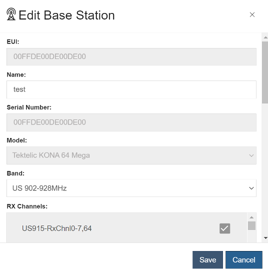
To modify Base Station information highlight the table row by clicking the Base Station Name then click the  button. This launches the Base Station Edit dialog.
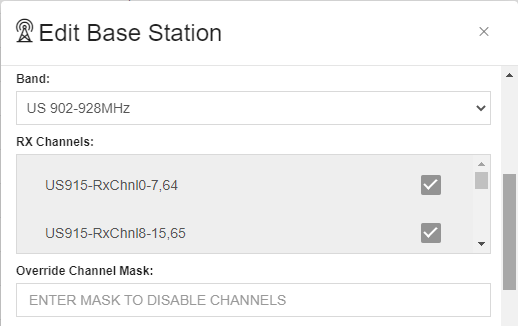
Overriding the Base Station Channel Mask
For advanced use only, this defines channel availability for the Base Station in question as an override to the default model-based ‘RX Channels’ configuration. Downlinks routed through the Base Station will only use mask-enabled channels. Likewise, uplinks heard only on mask-enabled channels are considered for ADR processing.
The mask value is expressed in bytes - with the LSB on the right - where the number of corresponding bits represents the minimum size channel plan for the Base Station’s region. For US915 and AU915 regions with plans of 72 fixed channels, the required length of an override mask is 9 bytes (72 bits).
For example, an override for either of these regions to use only the second bank of eight 125kHz uplink channels with the corresponding 500kHz downlink channel is expressed as 02000000000000FF00. Overrides defined for Base Stations using dynamic channel plans (EU868, IN865, and AS923) can vary in length, from at least 1 byte (8 bits) up to 2 bytes (16 bits), depending on the maximum number of supported channels.
Note
As an advanced feature with potentially high impact to channel plans of nearby Devices, careful planning of any Override Channel Mask change is strongly encouraged.
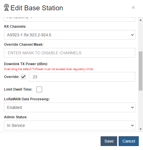
Overriding the Base Station Tx Power
For advanced use only, the Tx Power of a Base Station can be overriden for supported models and regions. If Tx override isn't supported, then the field is not shown. When supported, the field is shown with a warning message indicating that TX power should not exceed the regulatory limits of the region. Regardless of the configured Tx power, the applied value will not exceed the specified specified minimum and maximum values allowed. It will be ignored by the Base Station.
Supported Models And Limits
| Model | ISM Band | Max | Min | Default |
|---|---|---|---|---|
| MultiTech Conduit | AS923-1 | 23 | 1 | 16 |
| MultiTech Conduit AP | AS923-1 | 23 | 1 | 16 |
| MultiTech Conduit IP67 | AS923-1 | 23 | 1 | 16 |
Replacing a Base Station
Base Station Replacement allows users to replace existing Base Stations with new ones. This will move the site, viewshed, and case information from one Base Station to another making it easy to replace failed or misbehaving assets.
This can be done from the Base Station table. Simply select the base station you wish to replace and click the Replace button  :
:
The Base Station Replacement dialog is shown with the information populated from the source Base Station. This also associates the new Base Station with all the cases of the original Base Station.

Deleting a Base Station
A Base Station can be deleted by selecting a row and clicking on the  button. The user must type the Base Station EUI to confirm the delete. Only one Base Station can be deleted at a time. Deleting a Base Station will delete all records associated with that Base Station.
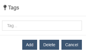
Base Station Tags
To modify Base Station tags, highlight the rows by clicking the Base Station Names then click the
button and then the "Edit Tags" menu item. This will launch the tag edit dialog which allows tags to be added or removed from the selected Base Stations. This also allows assigning tags to a single or multiple Base Stations. Base Stations can be searched by these tags through the table search.
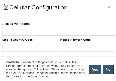
Configuring a Cellular Interface
To configure the cellular interface on a Base Station highlight the table row by clicking the Base Station Name then click the button. This button will only be available to click if the Base Station is running the latest compatible Netmore Base Station software. In order to configure cellular interface the Base Station must be connected to a LAN.
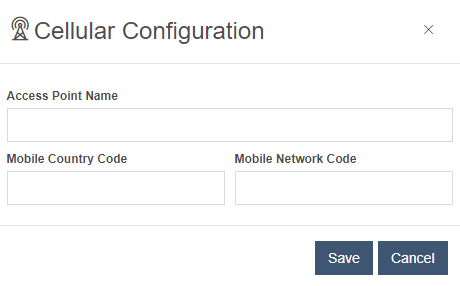
Type the required APN (Access Point Name) and click Save. Mobile Country Code and Mobile Network Code are only required for cellular interface configurations on Kerlink Base Station.
If the Base Station is already configured and connected through an active cellular interface, a warning message will be displayed: